
描述
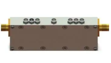
Cavity Combline Filters
Product Features
- High Q-factor, Low Insertion Loss: The cavity structure combined with the combline design achieves a very high Q-factor, thereby providing extremely low in-band insertion loss, with minimal impact on signal quality.
- Steep Out-of-Band Rejection: Possesses excellent out-of-band rejection capabilities, effectively filtering out unwanted frequency components and offering high selectivity.
- Excellent In-Band Flatness: Maintains good flatness of the signal response within the passband, ensuring distortion-free signal transmission.
- High Power Handling: The cavity structure typically has good heat dissipation capabilities and robustness, enabling it to withstand higher RF power levels.
- Good Frequency Stability: The choice of cavity dimensions and materials determines its frequency stability, usually performing stably over a wide temperature range.
- Compact Size (relative to waveguide): Compared to traditional waveguide filters, combline cavity filters can achieve smaller volume and lighter weight for a given performance.
- Highly Customizable: Filter parameters (such as center frequency, bandwidth, order, out-of-band rejection, etc.) can be flexibly designed and customized according to specific application requirements.
- High Reliability: The robust metallic cavity structure ensures long-term stable and reliable operation even in harsh environments.
Applications
- Cellular Base Stations (4G/5G): As a critical component in the RF front-end, used to selectively receive and transmit signals in specific frequency bands while suppressing interference from adjacent bands, protecting transceivers.
- Satellite Communication Systems: In ground stations and satellite transponders, used for frequency selection and channel filtering, handling high power and high Q-factor requirements.
- Radar Systems: In receiver and transmitter links, used for precise frequency selection to distinguish target signals from noise/clutter.
- Broadcast & TV Equipment: Utilized in television and radio broadcast transmitters to ensure signals are transmitted within allocated bands and suppress out-of-band emissions.
- Electronic Warfare & Reconnaissance: In broadband receive and transmit systems, used for precise frequency selection and signal separation.
- Test & Measurement Equipment: Serves as a reference filter for high-precision frequency selection, providing accurate filtering functions in laboratory and production testing.
- Microwave Point-to-Point Communication: In microwave backhaul links, used for separating and combining different communication channels.
- Aerospace & Defense: Applied in airborne and military communication/radar systems where stringent requirements for size, weight, performance, and environmental adaptability are essential.
Product Selection Table
| Part No. | Frequency Range(Hz) | Passband Loss(dB) | Passband Standing Wave | Out Of Band Suppression | Volume (mm3) |
|---|---|---|---|---|---|
| BKLLZ-610-670M | 610~670M | 0.8 | 1.5:1 | >70dB@570,710MHz | 160x66x21 |
| BKLLZ-775-882M | 775~882M | 1 | 1.5:1 | >70dB@709,949MHz | 60x38x21 |
| BKLLZ-1340-1485M | 1340~1485M | 1.2 | 1.5:1 | >70dB@1227,1598MHz | 160x38x18 |
| BKLLZ-1590-1735M | 1590~1735M | 1.2 | 1.5:1 | >70dB@l447,1847MHz | 160x38x18 |
| BKLLZ-2700-3100M | 2700~3100M | 1.5 | 1.5:1 | >55dB@2300,3500MHz | 85x21x13 |
| BKLLZ-3900-4500M | 3900~4500M | 1.5 | 1.5:1 | >55dB@3600,4800MHz | 85x17x12 |
| BKLLZ-5100-5700M | 5100~5700M | 1.5 | 1.5:1 | >55dB@4800,6000MHz | 85x15x11 |
| BKLLZ-13.6-18G | 13.6~18G | 1 | 1.6:1 | >70dB@11,20.6GHz | 70x13x9 |
| BKLZ-2.7-3.5G | 2.7~5G | 0.5 | 1.3:1 | >50dB@5GHz | 32x20x11 |
| >35dB@10GHz |

评价
目前还没有评价